本次美国代写是集成电路的一个Homework
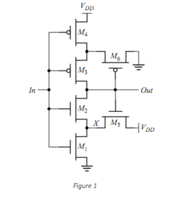
1. [CMOS Schmitt Trigger] Consider the CMOS implementation of the Schmitt trigger in Figure 1. Explain
why the threshold will change according to the state of the circuit.
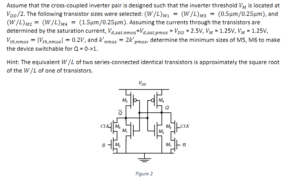
2. [Sizing of Clocked SR Latch] Consider the realization of a clocked SR flip-flop in Figure 2. It consists of
a cross-coupled inverter pair, plus 4 extra transistors to drive the flip-flop from one state to another and
to provide clocked operation. Consider the case where Q is high and an R pulse is applied. The
combination of transistors M4, M7, and M8 forms a ratioed inverter. In order to make the latch switch,
we must succeed in bringing Q below the switching threshold of the inverter M1-M2. Once this is
achieved, the positive feedback causes the flip-flop to invert states. This requirement forces us to
increase the sizes of transistors M5, M6, M7, and M8.
 3. [SRAM Analysis] Consider the 6T SRAM cell shown in Figure 3.
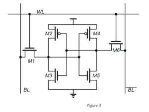 (a) Determine which transistors are involved in a Write operation, and comment on their relative
sizing when writing 1 and 0. Explain your reason.
(b) Determine which transistors are involved in a Read operation, and comment on their relative
sizing when reading 1 and 0. Explain your reason.