本次美国代写是一个电子硬件设计的限时测试
Overview: In this examination you will design, implement, and simulate digital hardware with sequential
and combinational logic to implement a pseudo-random number generator algorithm. This algorithm will
be implemented via hardware known as a linear feedback shift register (LFSR). These have applications
in generating simple randomness in gaming, cryptography, audio and signal processing.
An example of a 16-bit LFSR is shown below:
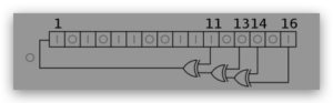
The depicted LFSR has XOR “taps” at positions [16, 14, 13, 11] (or zero-indexed: 15, 13, 12, 10).
In each clock cycle, the rightmost tap (which is known as the output bit) is XOR’d sequentially with the
next right-most taps and the result is “shifted in” to the left-most bit (the most significant bit (MSB)).
In this final exam you will implement an LFSR with the following specifications (essential features).
Note: this is the same base specification as what was used in the mid-term exam.
1. It will be 32 bits long (from position 0 (MSB) to 31 (LSB)), with taps at positions as determined:
a. Each of the unique adjacent 2-digit numbers in your N number modulo 32.
b. The 32 bit (position 31, the LSB).
c. For example, if your N number is 01123497, you will have taps at positions
i. [01, 11, 12, 23, (34 % 32 =) 2, (49 % 32 =) 17, (97 % 32 =) 1] (“1” value is not unique)
ii. = [1, 2, 11, 12, 17, 23, 31] (31 comes from point 1b) – remember these are zero-indexed
2. Top I/O:
a. clk: input
b. rstn: active-low reset signal
c. data_out: 8 bit output
d. get_random: input 1 bit control signal
e. 1-bit input “load_seed”
f. 8-bit input “data_in”.
3. Unless otherwise specified, the LFSR will update (shift-in the XOR result) upon every clock
cycle. The bits shift into position 0 (the MSB).
4. If “output” is requested by setting “get_random” to 1, the least significant 8 bits will be output to
“data_out” in the next clock cycle, the next 8 in the next clock cycle, the next 8 in the next cycle,
and the most significant 8 bits will be output in the final (fourth) cycle. No LFSR shifts will occur
during this output sequence. At all other times the “data_out” will be all zeros.
a. NOTE:
i. If the get_random signal is held high for longer than 4 cycles then the LFSR
would presumably immediately begin exporting the contents again, and so it
wouldn’t perform any shifts, however there might be one clock cycle where
the internals could shift. This part of the spec is upto to you.
ii. Similarly if get_random is high for less than 4 cycles, it should continue with
the output until it is completed.
5. Reset signal “rstn” will reset the LFSR contents to 0x02468ACD
a. (Reset signal “rstn” should always take precedence over every other signal)
6. If “load_seed” is set to 1, the lower 8 bits will be loaded into the LFSR from “data_in” in the first
clock cycle, the next 8 in the next, the next 8 in the next, and the upper 8 bits will be loaded in the
final (fourth) cycle. No LFSR shifts will occur during loading. After loading, shifts will resume as
normal.