本次美国代写是关于数字片上系统相关的一个Assignment
1. Function Description
In this lab you are going to design a small digital system, which will be called the ‘processor’ in this lab. The function of the processor can be mathematically expressed as the following equation:
𝑓𝑓(𝑥𝑥) = 𝑡𝑡𝑡𝑡𝑡𝑡ℎ(𝐶𝐶 ∙ 𝑡𝑡𝑡𝑡𝑡𝑡ℎ(𝐴𝐴 ∙ 𝑥𝑥))
where 𝑥𝑥 is a 8-by-8 input matrix, 𝑓𝑓(𝑥𝑥) is the 8-by-1 output matrix, 𝐴𝐴 is the 8-by-8 coefficient matrix,
𝐶𝐶 is the 1-by-8 coefficient matrix, 𝑡𝑡𝑡𝑡𝑡𝑡ℎ(∙) is the regulation function tanh(𝑥𝑥) = (𝑒𝑒𝑥𝑥− 𝑒𝑒−𝑥𝑥)/(𝑒𝑒𝑥𝑥+ 𝑒𝑒−𝑥𝑥).
The process of this function includes several steps:
Step1: Calculate the matrix dot product 𝐴𝐴 ∙ 𝑥𝑥, the output is a 8-by-8 matrix 𝐵𝐵.
Step2: For each element 𝐵𝐵𝑖𝑖,𝑗𝑗 of matrix 𝐵𝐵, calculate the 𝐵𝐵′𝑖𝑖,𝑗𝑗 = tanh�𝐵𝐵𝑖𝑖,𝑗𝑗� to get 𝐵𝐵′ , which is an 8-by-8 matrix.
Step3: Calculate the matrix dot product 𝐶𝐶 ∙ 𝐵𝐵′ and we get a 1-by-8 matrix 𝐷𝐷.
Step4: For each element 𝐷𝐷𝑖𝑖,𝑗𝑗 of matrix 𝐷𝐷, calculate the 𝐷𝐷′𝑖𝑖,𝑗𝑗 = tanh�𝐷𝐷𝑖𝑖,𝑗𝑗�, and 𝐷𝐷′ = 𝑓𝑓(𝑥𝑥) is the final output of the function.
2. Processor Architecture Description

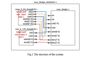
As shown in Figure 1, the whole system includes your custom-designed processor, an 8-bit single port RAM (random access memory) with 64 depths (means it can store 64 numbers, and each number is 8-bit), and one 8-bit single port ROM (read-only memory) with 128 depths. All the data in this lab are signed 8-bit fixed-point numbers in two’s complement notation (the fixed-point is between the 5th and 6th). In the testbench file (we provide you a template), besides your processor, you also need to instantiate the two memories (the codes for the memories, sram_8_64_freepdk45.v and rom_8_128_freepdk45.v are provided). The connections between the memories and your processor are shown in Figure 1.
The definitions of the ports are listed in Table 1.
The matrix A and C are pre-stored in the ROM (load the data using the $readmemb command in the initial block). Since this memory is read-only, you cannot write data to back to the ROM. The input matrix x is pre-stored in the RAM (also use the $readmemb command in the initial block). The RAM is also used to store the intermediate data (e.g., B, B’, D). In this lab, we limit the maximum size of single register array (no larger than 16*8 bits), thus we try to push you to use the RAM to store the intermediate data. So the whole process would be your processor read data from the memories, do the calculations, store intermediate data back to the RAM, read new data, do the calculations, write back to the RAM, …, finally write the 8-by-1 output matrix 𝑓𝑓(𝑥𝑥) to the RAM (addresses are from 0 to 7).
The initial address of x and A are decided by 𝑡𝑡𝑎𝑎𝑎𝑎𝑎𝑎 = (𝑖𝑖 − 1) + (𝑗𝑗 − 1) × 8, where 𝑖𝑖 is the row and 𝑗𝑗 is the column. For example, 𝑥𝑥35 or 𝐴𝐴35 are stored at address (3 − 1) + (5 − 1) × 8 = 34. The initial address of C is decided by 𝑡𝑡𝑎𝑎𝑎𝑎𝑎𝑎 = 64 + (𝑖𝑖 − 1) × 8 + (𝑗𝑗 − 1), which means the C is stored at the bottom of A. You are free to decide the address of intermediate results.


